
Power Plants and Process Facilities have millions of moving parts and diagrams show how they work. Few parts are more important than valves. A valve controls the flow of air or liquid through the piping. So, to understand a system shown on a process flow diagram (FD) or a piping and instrument diagram (P&ID), you must understand the valve symbols. The valve symbols can show you the type, how they operate, and more.
A variety of industries use valves, but in this article, we will discuss the most commonly used valves in a power plant and process facility setting.
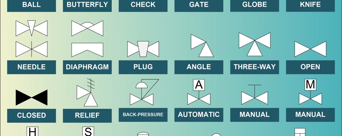
In alphabetical order (graphical examples do not represent every configuration):
A Ball valve uses a hollow, rotating ball with a hole going through the ball. The hole lines up with the inlet/outlet when it is open. And the solid sides of the ball line up with the inlet/outlet when the valve is closed.
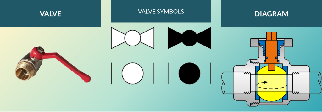
This type of ball valve symbol looks similar to the globe valve. The ball valve symbol has a larger circle indicating the ball inside the valve.
A butterfly valve rotates a flat disk to block or unblock flow through the system.
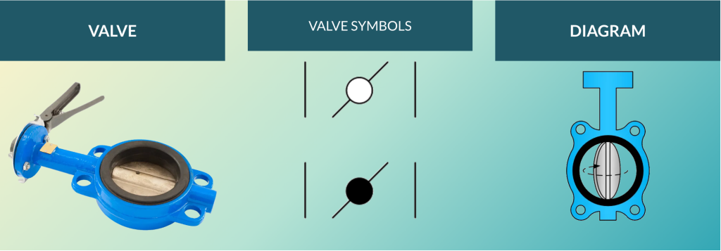
These valves are dampers (not all dampers are butterfly valves). A damper is a valve or plate that stops or regulates flow. Therefore, you may find a damper on an FD or P&ID showing one or more butterfly valves.
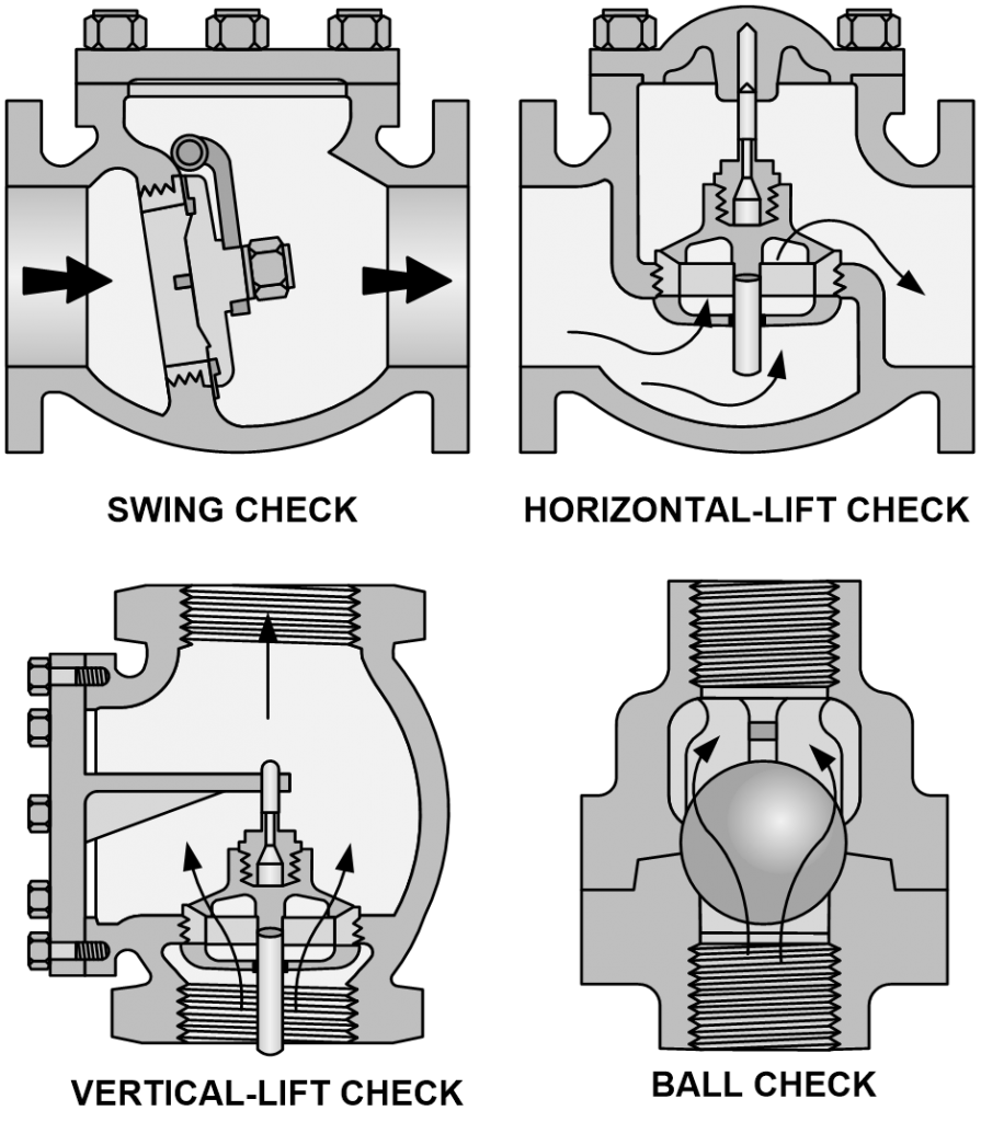
A check valve controls liquid or air by allowing it to flow in only one direction. Also known as a non-return valve or a one-way valve. Below is the check valve symbol that may be displayed.
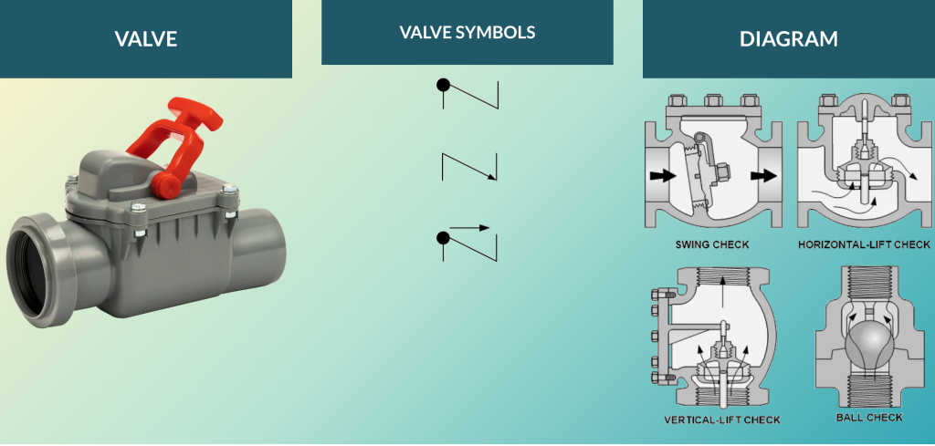
There are several arrangements for check valves, as shown in the diagram below. The main indicator of this symbol is that the flow is one-directional.
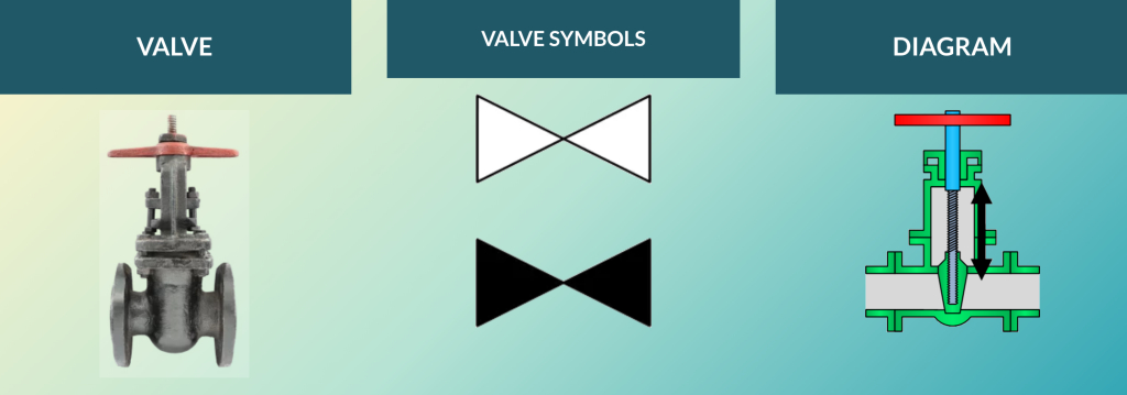
A gate valve is one of the most used types of valves in a Power Plant. These valves operate by lifting a gate up and down to open or close the valve, thus controlling flow through the system.
A globe valve operates by a barrier, such as a plug, moving up or down to seal a stationary ring.
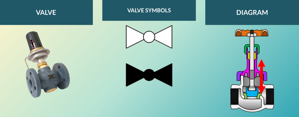
Similarly, this symbol shows a circle just as the ball valve does. The globe valve symbol has a smaller circle indicating the shape of the valve casing rather than indicating the presence of a ball inside the valve.
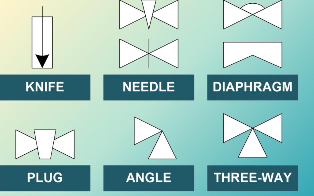
Although not as common, shown below are additional valve symbols you might encounter on an FD or P&ID.
The state of a valve is typically either open or closed. On an FD or P&ID, valve symbols are white to show that they are normally open, while completely black symbols show that they are normally closed.

Furthermore, the symbols can indicate the valve operation. The operation of valves can be either Automatic, Manual, Pneumatic (Diaphragm), Motor, Hydraulic, Solenoid, Pneumatic (Rotary Piston), Balance, and more. Symbols for operations are in the graphic below.
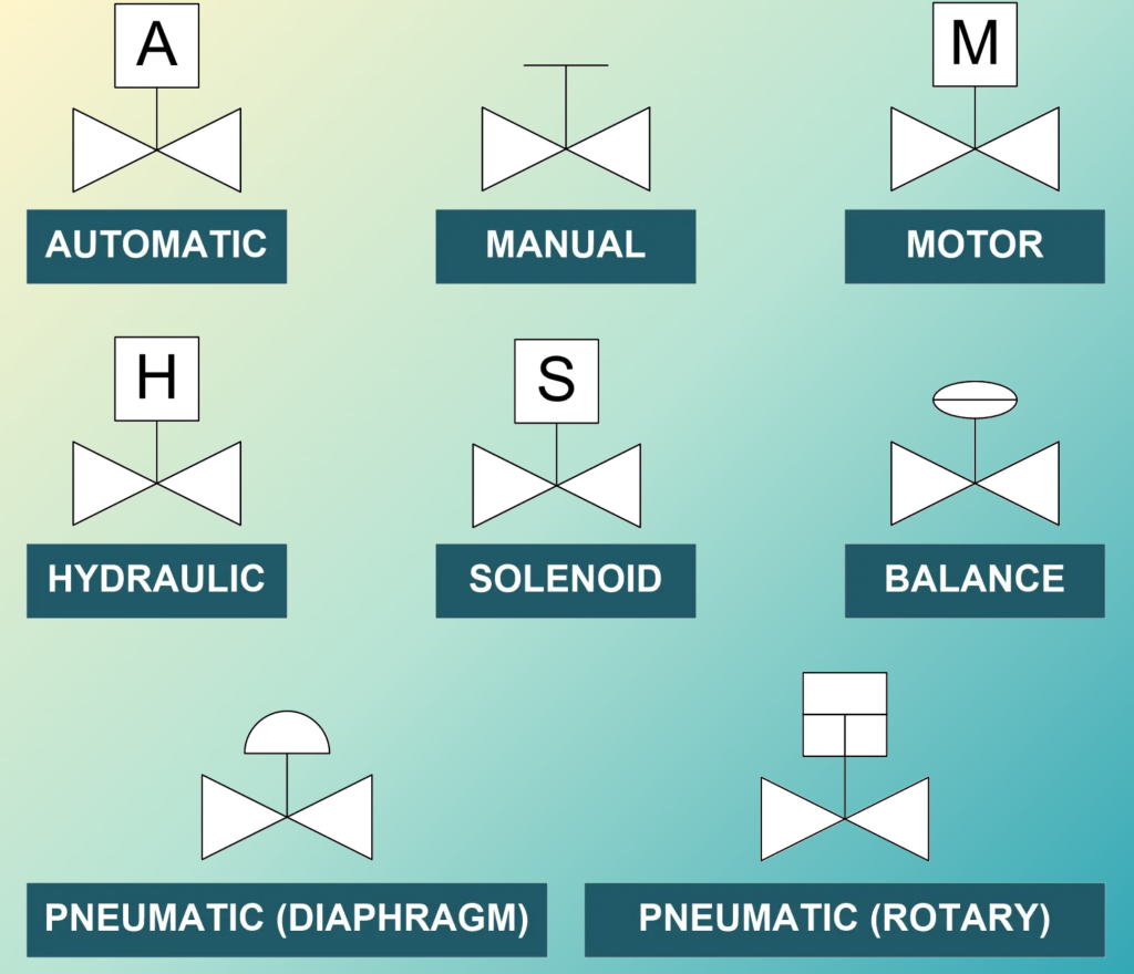
Automatically-operated valves are specialty valves fitted with actuators that are often controlled by temperature or flow sensors. These valves can also include pressure or temperature gauges.
Manually-operated valves open/close by hand, which is why many operators call them hand valves. This happens when an operator spins a valve’s handwheel clockwise or counterclockwise to position the valve.
Motor-operated valves open/close with electric motors. This is usually due to the size of the valve or the criticality of the valve position, such as a flow control valve.
Hydraulically-operated valves open/close using the hydraulic fluid pressure. These types of valves are used when a large amount of force is required to reposition the valve.
Solenoid-operated valves use an electromagnetic solenoid coil to open or close the valve. Meanwhile, the solenoid coils are activated by being electrically energized (to stop the flow) or de-energized (to allow the flow), or vice versa.
Balance-operated valves regulate pressure and flow to attain hydraulic balance in the system.
Pneumatic-operated diaphragm valves use compressed air to vertically reposition the valve by applying the compressed air to a diaphragm that repositions the valve. Therefore, these valves use the combination of compressed air, a diaphragm, springs, and solenoid valves to achieve the correct valve position, and corresponding flow through the system.
Pneumatic rotary valves use compressed air to cause a linear or rotary motion for the operation of specific types of valves.
Additionally, valves can be relief or backpressure valves.
Relief or safety valves protect a system from overpressure. These valves open to relieve system pressure when it detects a certain pressure.
Back-Pressure valves are used to regulate pressure upstream of the valve in the system. These valves modulate to maintain the desired system pressure.

FCS has been using valve symbols, among many others as part of training documents to create FDs and P&IDs for over 25 years. We have in-depth diagrams breaking down each type of valve and symbol for easy-to-read and clear documentation for your facility along with electrical drawing symbol guides.
We do! Our team here at FCS uses existing documentation as well as walking-down systems to create accurate training materials for our clients. Therefore, ensuring a thorough review of the system. Technical Documentation helps training become contextualized through consistent use of symbols and terminology. This improves plant operations by equipping trainees with the correct knowledge to operate the necessary equipment safely, effectively, and efficiently.
If you would like to learn more about FCS’s training materials, contact us today!