In March 2020, FCS published a blog introducing the fundamentals of Zero Liquid Discharge (ZLD) solutions to wastewater management. Today, we would like to delve deeper into the subject by exploring a technology that can play an essential role in ZLD sites: Air-Cooled Condensers. Anyone familiar with the “three Rs of recycling” should know that of the three – reduce, reuse, and recycle – the most important is reduce. ZLD projects possess some of the same principles and reducing the amount of water that is accounted for by a ZLD project is certainly going to ease the process. That is where Air-Cooled Condensers come in to play. A 2012 study conducted by EPRI concluded that a dry-cooled plant would save from 95%-75% of the water used by a wet-cooled plant. Clearly, that reflects reduction with a capital R.
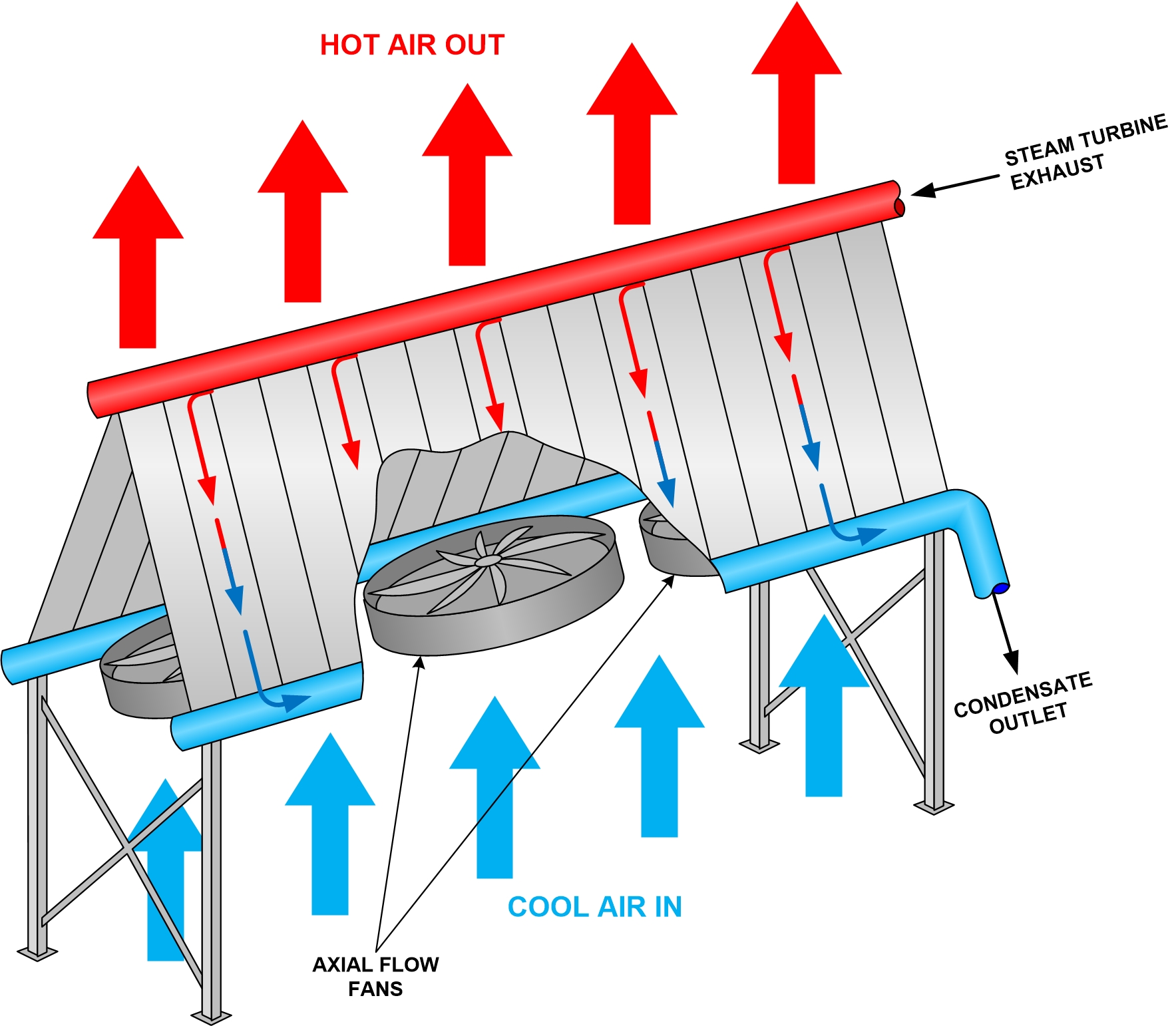
A typical Air-Cooled Condenser (ACC) is made of modules arranged in parallel rows. Each module contains fin tube bundles. An axial flow, forced-draft fan located in each module forces the cooling air across the heat exchange area of the fin tubes. Thus, the steam is directly condensed inside the air-cooled finned tubes without using an intermediate surface condenser (cooling tower) or circulating water system. As a result, it eliminates the water usage associated with the operation of those systems. The condensate collecting manifold collects the condensate produced in the ACC, and transfers it to the condensate collecting tank, which is part of the condensate system. A cross-section view of a typical, A-frame type condenser is pictured below.
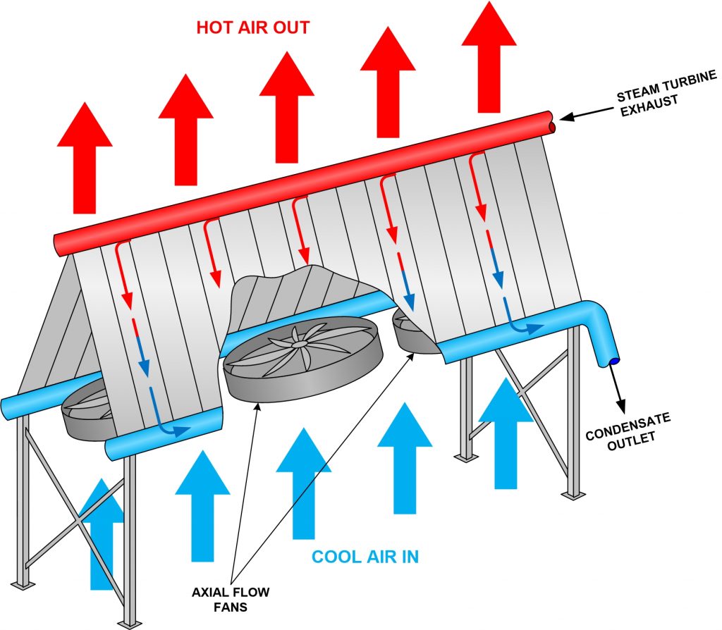
An ACC operates at a vacuum – just like a conventional condenser does. As with conventional condensers, air and non-condensable gases enter the steam system in the same manner (system and turbine leakage). These gases are expelled in a separate section of the ACC – typically referred to as the “secondary section” by air ejectors or vacuum pumps.
ACCs supplied by most every manufacturer share these basic factors. The differences between them are primarily in the arrangement, shape, and material of the condenser’s finned tubes. Some condensers utilize a single row of tubes, while others use multiple rows. Different tube shapes include round, oval, and flat. Materials used include aluminum fins brazed-on flat bare tubes coated with aluminum, or oval galvanized finned tubes bundles. These are generally accepted as the two most reliable materials to resist corrosion and erosion in power plant applications.
There are other factors considered in the decision to use an ACC besides the elimination of cooling water. Siting, for example, often lends itself to ACC utilization. ACCs allow plants to be constructed in areas where there is a lower availability of water. In fact, some ACC installations are selected because of their proximity to plant fuel sources and/or transmission lines, which can significantly lower operating costs. These factors can help offset the higher capital costs for ACCs.
An example of this type of decision-making is provided by a recent agreement to construct a 900-MW combined-cycle natural gas turbine plant in Alberta, Canada. While the cooling requirements for a plant of that size would often fiscally preclude the use of ACCs, thGet Custom Training For Your Plant Now 🡆is proposed plant would be situated near both high-voltage transmission lines and significant natural gas production facilities. The location, then, affords the use of ACCs.
Since 1999, over 20 GW of new U.S. energy capacity has utilized dry-cooling. So, whatever the reasoning used to deploy an Air Cooled Condenser, it is clear that this technology will only grow in market share.