
Power plants and process facilities have hundreds of moving parts and associated diagrams showing how they work. Many components are electrical. Therefore, to understand how a power plant works, you must be able to understand electrical drawings and the symbols an electrical drawing uses to represent parts of the circuit.
Usually, drawings show liquid flowing through pipes to show the symbols on a drawing as they would be to allow flow. Electrical drawings are different. These drawings typically show components in their de-energized state. For Example, a breaker symbol is shown as follows:
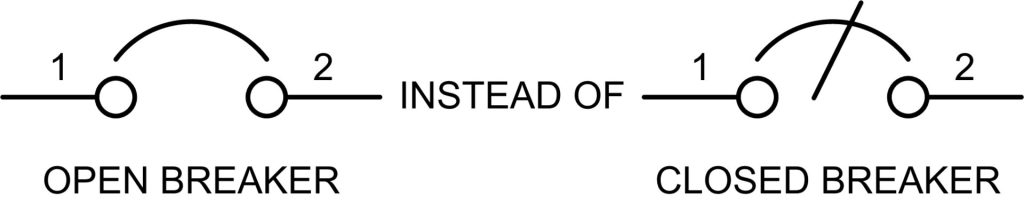
In electrical one-line diagrams, the drawing is as shown on the left – de-energized. This is common with electrical schematics and is integral to understanding the drawings.
For fluid systems, it is easy to think of going from a high pressure to a lower pressure. This is how water flows through pipes. In electrical systems, you can think of the same relationship in that voltage is pressure and current is flow. So, a battery or DC circuit will flow from high voltage at the battery negative posts to lower voltage at the positive posts. The current flow is the “water”.
Electrical distribution normally follows a typical path. There is a source, which can be either the “grid” or a generator of some kind. This then flows to a transformer, through circuit breakers to a bus. The symbol for a transformer is as follows:
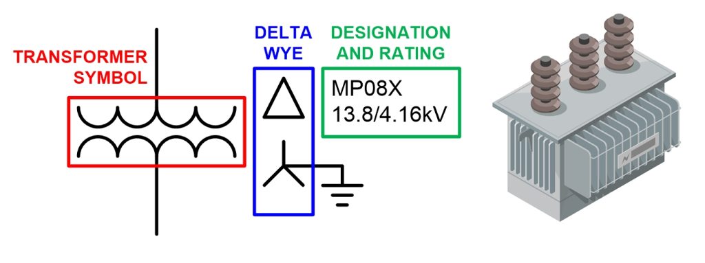
The electrical drawing symbol for a transformer is in the red box. Voltage comes in the top and goes into the primary windings, then voltage is induced into the secondary windings. In this case, the transformer is a Delta-Wye configuration, is labeled as MPO8X, and steps down the voltage from 13.8 kV to 4.16 kV.
Circuit breakers and fuses are protection devices that are used to interrupt current flow by creating a physical separation between two conductors. Circuit breakers can be designed to interrupt the circuit under many different conditions. Overcurrent is the most common, but under frequency, over-voltage, under-voltage, etc., can also be designed into the circuit.
Fuses work only on overcurrent. Normally made of a thin metal or different metals that heat at different temperatures or currents, the fuse opens when the current rating is exceeded. Some fuses must be replaced when they “blow”. Some can be reset with a switch. The symbol for a circuit breaker (in this case a three-phase circuit breaker – 1, 3, 5) and three fuses (2, 4, 6) are shown:
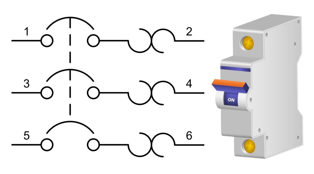
The three dotted lines connecting the circuit breaker symbols mean that the circuit breakers operate together as one unit. As can be seen by the picture of the circuit breaker, there is only one actuator on the front. The actuator moves all three contactors (1, 3, 5) at the same time. The fuses act independently of each other.
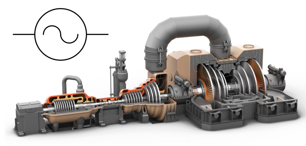
Generators have a special symbol as well in electrical drawings. The symbol for an AC generator is shown below ( A large steam-driven turbine generator is also shown):
Batteries generate voltage chemically. Batteries are typically grounded or have the negative and positive terminals tied together. Therefore, there are two common symbols for batteries in a circuit:
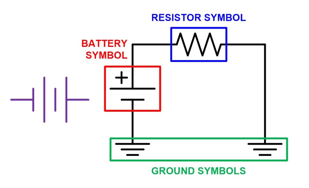
The first symbol is a typical battery symbol. The larger lines are the positive plates and the smaller lines represent the negative plates in the battery. The second drawing shows the negative terminal tied to the ground and the positive terminal going through a resistor to the ground.
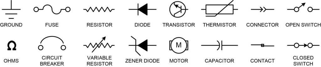
There are hundreds more electrical drawing symbols for drawings such as those shown below:
FCS has been using electrical symbols among many others as part of training documents to create electrical one-line diagrams for over 25 years.
Our team uses existing documentation as well as walking-down systems to create accurate training materials for our clients.
If you would like to learn more about FCS’ training materials, then contact us today!
