
For most of us born before 1990, controls or logic diagrams remind us of Indiana Jones trying to decipher some ancient scroll. The language is foreign to us, and computers have always been “magic” devices that just did things. Distributed Control Systems (DCS) and Programmable Logic Controllers (PLCs) have been part of power plant operations for decades, and have merged their way into our everyday life in our automobiles, appliances, pockets in the last 20 years. Despite this, your average citizen (and operator) don’t understand how they work and don’t understand how to use it effectively or what to do when something goes wrong.
My entire operational career, we had a term for anything that involved electrical or electronic controls. It was Pure (I’ll let you guess) Magic. Pumps, valves, hydraulics, air signals? Understood it all. Relays, starters, zener diodes? Might as well have pulled a rabbit out of a hat.
Then I graduated to the control room. There, I entered the Matrix. Digital controls and databases. Worse, I not only needed to learn it, but I was in charge of it. If someone wanted to do work on it, they had to come to me for authorization. It was like Laurence Fishburne was whispering in my ear “No one can be told what the Controls Scheme is. You have to see it for yourself.” So, I had to learn it, in fact, I’m still learning it. In reality it’s not magic at all. The trick with computer systems is understanding the language, and, like learning a foreign language, it takes time, and use.
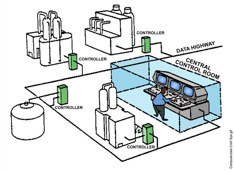
Distributed Control Systems tie individual systems together over a network. There are different names for the network, but often it is referred to as a “Data Highway.” It connects sensors and controllers across the plant to the control room using digital signals instead of electrical or pneumatic signals. What used to require miles of piping or wires is now passed through fiber optic cables, and instead of walls of gages and meters, the entire plant can be displayed on a computer monitor. Some newer systems even utilize wireless communications to eliminate the need for fiber optic connections between systems.
The use of a DCS also allows equipment operation to be centralized from the control room, or anywhere the DCS has a computer workstation. Conversion to digital controllers for motors and breakers, and electrical motors on valves make remote operation over the network as easy as configuring your smart house. Sounds like an episode of Star Trek, doesn’t it?
If you have digital controls in your plant, you’ve likely heard the term “4 to 20 milliamp” a time or two. In a nutshell, computers use very small electrical inputs. For the computer to provide an indication, the actual parameter must be converted into this usable signal. There are multiple ways of converting parameters in the plant, but one of the most common is the Linear Variable Differential Transformer (LVDT). The LVDT utilizes a magnetic core and electrical windings to produce an output based on the movement of the magnet.
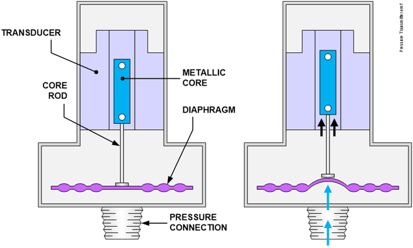
Many indicators work on the same principle, but individual technology can get quite interesting. For example, the vortex flowmeter uses the disturbance in a fluid to create a pressure signal that can be sensed by a detector. This is converted to a 4 to 20 milliamp (or similar) signal. While this sounds like PFM, the base technology is the same. Create a pressure, then use a piezoelectric crystal or diaphragm type measuring device to convert that signal to an electrical one. What used to be a pneumatic output is now just an electrical one. These devices are referred to as “Field Devices.”
These Field Devices can do more than just send a signal to the DCS. The transmitters used to sense system parameters can both locally display the parameter, and can also use the local controllers to directly signal the output device utilizing a “Current Loop,” where the power supplying the controller is also supplied to the output control device, such as a valve positioner, or variable frequency drive on a motor. This removes extra power cabling from the installation, and reduces noise feedback in the control signal.
The 4 – 20 mA signal generated in the current loop is directly proportional to the 0 – 100% range of the measured parameter. That same 4 – 20 mA signal is sent to the local controller, which performs the calculations and comparisons to drive the desired output signal that will in turn drive the proper adjustments. A quick example:
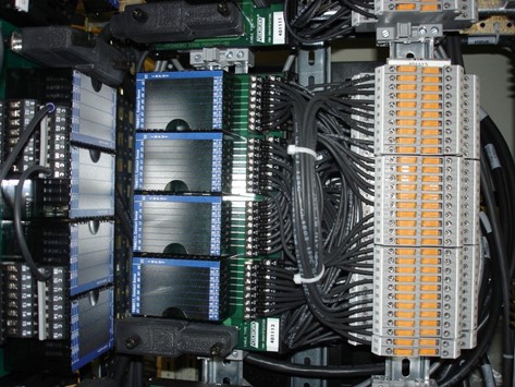
Once an electrical signal is produced it is sent to an Input/Output Drop Box (IODB). Similar to the router of your computer, it takes signals in and moves them along the highway, or receives signals from the highway and sends them back down to the field devices. Often, the IODB will be part of a control unit. The control unit can be integrated into the machine such as a PLC, or can be in a separate cabinet or “enclosure,” either way, the controller is basically a stand-alone computer. The information received from the input side of the IODB is processed in the computer. Based on the program built into the computer, this information is either simply passed along to the DCS for display on the workstations, or can be used to provide an output signal to cause an action (through the Output portion of the IODB).
Controller output signals can be used to cause actions such as initiating an alarm, starting a pump, or positioning a valve. Not only this, but the information received by the controllers can be used as inputs to a digital control “scheme,” which takes the information provided by the field devices, compares it to a programmed setpoint, and then provides an output back to cause an action. Digital control schemes are used in most modern processes that require constant adjustment to maintain the desired output. A great example of a digital control scheme is the cruise control in your vehicle. The speed you select is the setpoint, and the speed provided by your vehicle’s speedometer is the signal from the “field device.” The cars computer will take that signal and provide a control output to your fuel injection system to speed up or slow down. Digital control schemes are a topic in themselves.
Digital controls are extremely beneficial to any multi-unit process. The larger the operation, the more benefit can be had from digital controls. One benefit is the removal of moving parts and mechanical joints associated with relays, switches, gage lines, and pneumatic controllers. In older systems, each measured parameter (pressure, temperature, level, etc.,) required a dedicated connection and transmission path (pipes or wires). Then, the control device for each portion of the control loop required a dedicated transmission path (piping or wiring) and power supplies. The digital control system can easily be set up to replace these individual lines with transducers that collect multiple types of data from one connection and process that through digital signals to the data highway.
Fiber optic cables can easily be run from one side of a large complex to the other, and even better, remote equipment can speak to the network through a wireless connection, much like your “smart home.”
The other benefit of digital controls is the amount of information available and the speed at which it processes it. Older systems had a lag associated with both the age of the control device (such as a pneumatic controller or level indicator) or the distance the equipment was from the controller. A digital signal updates every few microseconds, and provides an EXACT indication to the operator.
Along with the speed of processing, the use of digital controls also provides constant retention of data. Every time the signal is updated, it is recorded. If an alarm is actuated, the exact conditions at the time of the alarm can be recalled by the operator. The DCS can be configured to display graphs to allow monitoring trends and help maintenance personnel troubleshoot equipment problems.
Often when a system does not respond the way it is expected, an operator will assume that the computer “messed up” and will take manual control to correct the issue. In this case, it is important to remember that the computer will only do what it is told to do. If something is not working correctly, there are a few steps to take:
For more information on Distributed Control Systems, digital control schemes, or to see how we can help improve your operations.