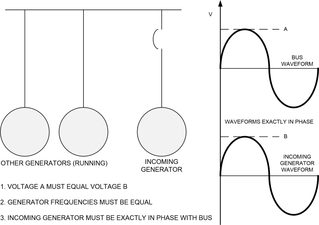
Many large AC generators operate in the bulk electric system (BES), each feeding power to the system. Each generator must satisfy three conditions in order to operate in such a system.
If any of these conditions are not met, severe damage to the generator may result. The system may also be affected. Generally, the power of the system is much greater than that of anyone generator. Therefore, the effect on the system is usually slight.
The reason for these requirements may be difficult to understand because of the electrical theory involved. To understand the frequency and phase angle requirements, it may be helpful to think of the electrical system as a column of marching soldiers, with each generator as one soldier. As long as each soldier marches at the same pace (frequency) and in step (in-phase) the column marches along with no problems. The column disrupts if one soldier tries to march at a different pace or out of step.
The third requirement that each generator must also satisfy (voltage) does not fit into the analogy of the marching soldiers. Each must supply power to the system at about the same voltage. Minor variations are permitted, however, and indeed are sometimes required.
The illustration below shows incoming generator requirements.
Normal Operation automatically satisfies frequency and phase angle requirements. After the main and field breakers of a generator close, it becomes synchronized or paralleled to the system. The electromagnetic forces created when the generator synchronizes to the system will “hold it in step.” This is true even if the steam valves supplying steam to the turbine driving the generator to close. It then will take power from the system and act as a synchronous motor, operating at 3600 rpm. Note that this is a different situation than that described previously regarding induction motors. In this case, because the exciter current remains, the rotor will continue to rotate at the same speed as the magnetic field in the armature, 3600 rpm.
The generator’s most critical time of operation is during startup when it synchronizes to the system.
When a turbine generator is first started up, the main breaker and the field breaker are both open. The field breaker usually closes at about the rated speed. The field breaker supplies the DC current to the generator rotor to magnetize it. Once this happens, it produces a voltage, but no current flows until the main breaker closes.
The frequency of the system measures in Hertz, but the speed or “frequency” of the turbine‑generator measures in revolutions per minute (rpm). For all 3600-rpm turbine‑generators, dividing the speed in rpm by 60 determines the frequency of the generator.
The turbine controls will hold the speed of the turbine‑generator very close to the frequency of the system, but usually, there will be a small difference of perhaps 0.1 Hertz. The turbine controls allow the operator to make the fine adjustments of turbine speed necessary to exactly match the frequency. Some units have automated controls that will match the frequency without operator intervention.
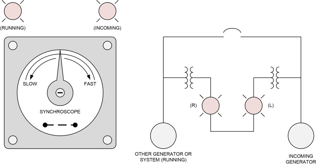
The operator uses a meter called a synchroscope (see above) to match the generator and system frequencies. The synchroscope resembles a clock with only one hand. That hand rotates clockwise when the frequency is greater than the system frequency and counterclockwise when it is less. The speed at which the hand rotates is the same as the difference in frequencies, converted to rpm. Thus, if the turbine‑generator were operating at 3601 rpm and the system frequency were at exactly 60 Hz (equivalent to 3600 rpm), the hand would move clockwise at 1 rpm. When the frequencies match exactly, the hand would stop rotating.
The synchroscope also provides another valuable indication, phase angle. The generator may be at the same frequency as the system and yet be “out of phase” with the system. Referring back to the analogy of the marching soldiers, one soldier may be marching at the same cadence as the rest of the column. However, he could be putting his left foot down while the rest of the column puts their right foot down. He is “out of phase.”
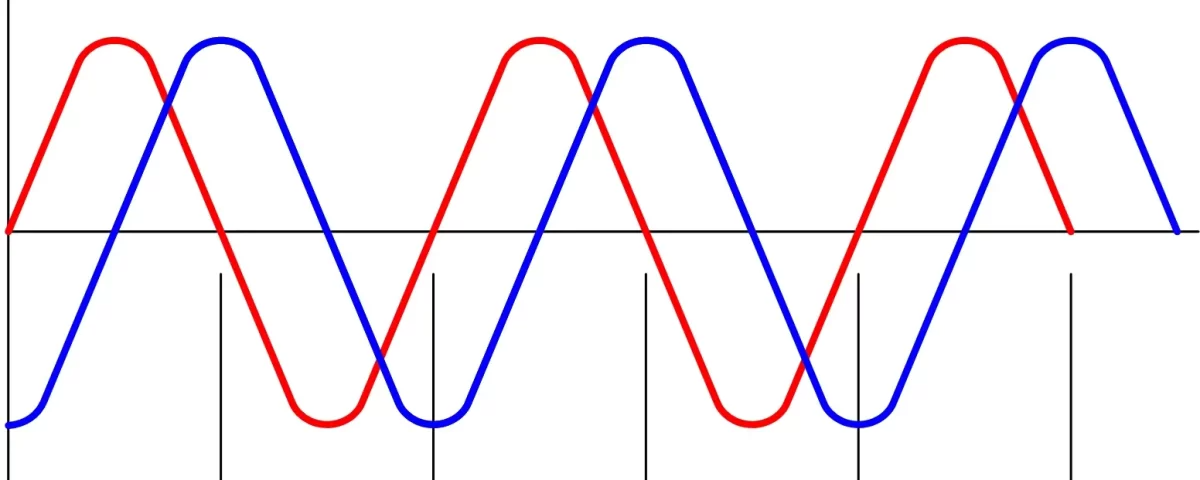
Electrically, the illustration below shows the concept of phase angle which generally shows in degrees.
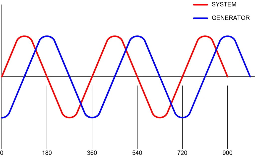
This figure shows two “sine waves.” The voltage of any generator has such output for each phase. Thus, the figure shows the voltage change for one phase and the same phase of the system. The two have the same frequency, but their horizontal displacement means they are not in phase. The operator can get the two in-phase by either speeding up or slowing down the generator just long enough to make the two curves overlap.
The position of the hand of the synchroscope shows the phase angle between the system and the “incoming”. When it points straight up (12 o’clock), it indicates that the generator and the system are in phase; that is, the phase angle is zero. When the position is straight down (6 o’clock) the phase angle difference is 180 degrees, which is the worst condition.
The operator adjusts the speed of the turbine-generator to obtain a position of the synchroscope hand of 12 o’clock, with the hand stopped, to close the main generator breaker. Most units have a key type interlock which requires the synchroscope to be in service as a permissive for closing the main breaker. In practice, it is desirable to have the speed of the turbine‑generator slightly greater than the system frequency, such that the synchroscope is traveling slowly (about 1/2 rpm) in the “fast” direction. In this case, the main breaker closes “on the fly” just before the hand reaches 12 o’clock (at about 5 minutes before 12). The system is parallel or synchronized once the breaker closes.
The generator can obtain severe damage if the main breaker closes with the generator and system out of phase or with a large difference in frequency. This is because very large currents will flow in the windings of the stator causing damaging heat, and tremendous forces will result as the system literally “pulls” the generator into synchronization. Often protective relaying prevents the breaker from closing unless phase angle and frequency differences are very small. The operator should not, however, rely upon this protection.
There is a third requirement for synchronizing the generator. The voltage must be very close to that of the system. Generator voltages are generally around 13 kV to 24 kV and step up to 130 kV to 230 kV by a step‑up transformer. The main generator breaker is between the transformer and the bus. The operator measures the running system voltage on the bus side of the breaker. They measure the incoming voltage on the high side of the transformer or the transformer side of the breaker. The operator must match the generator voltage to the running voltage as well as match system frequency and phase before closing the main generator breaker.
The operator may find it necessary to adjust the generator speed and then voltage several times to synchronize. Before synchronization, the voltage increases if the speed increases. Conversely, the voltage decreases when speed decreases. This is because how many lines of magnetic flux cut the conductor per second determines the voltage. The generator voltage may change before the breaker closes. This can be accomplished by adjusting either speed or the strength of the field.
The generator can be severely damaged if there is a substantial mismatch of voltage with the system. This can occur because there can be very high currents induced in the stator which cause damaging heat.
After the generator breaker closes, varying generator voltage controls the amount of reactive power or VARs that the generator supplies to the system or uses from the system. If the voltage increases slightly above the system voltage, the generator will supply VARs to the system. At voltages below the system voltage, the generator will use VARs from the system, and when the voltages are the same, the generator will neither produce nor use VARs.
In most operations, the generator will supply VARs to the system (higher voltage) and operation in this mode is called lagging or “buck”. Occasionally, during nights or weekends or usually, when the system load is low, the system will not require VARs and the generator may require to “use up” some of the excess VARs in the system. When operated in this mode, the generator is said to be leading “boost”. The system dispatcher usually directs each plant in the system to produce or use the proper number of VARs similar to the way he directs the proper load in watts to be carried.