

In Part 1 and Part 2 of this series, we discussed the basics of modern microprocessor-based controls and Distributed Control Systems (DCSs). Now that you’ve seen inside the Matrix, we are going to take a look at a sample DCS control scheme and the Ladder Logic used to program the function of this control.
The individual manufacturers will have specific nuances in their programming “code” (language) and how their logic is set up. However, the standard for programming ladder logic is from the International Electrotechnical Commission (IEC) 61131 (PLCs) and is titled IEC 61131-3.
As we have previously discussed, a Programmable Logic Controller (PLC) is a small computer that receives inputs from a variety of devices and provides indication and control output signals to both local and remote controllers and displays. A Distributed Control System (DCS) is a network of connected devices that control an entire process, whether that be a Boiler Plant, an Electrical Distribution System, an industrial process (packaging for example), or all of the above.
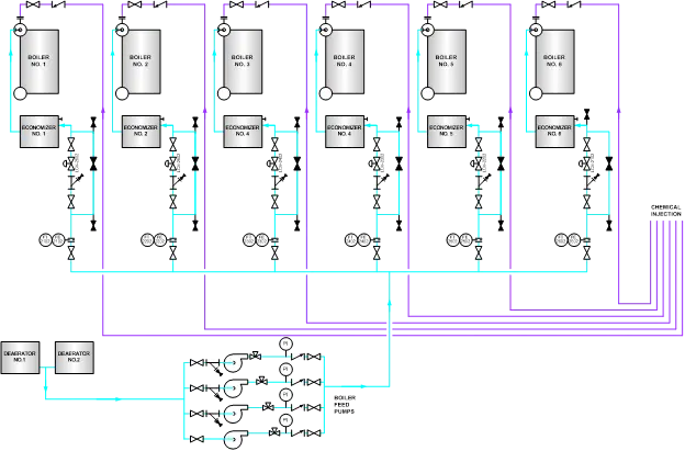
Let’s take a look at a control circuit and put together what we’ve discussed so far. The range of functionality for a microprocessor is only limited by the programmer and the size of the CPU, but for our sake, we are going to focus on a simple logic circuit. For our example, we are going to use a Feedwater Control Circuit. For our system, the Distributed Controls System uses a computer called the “Plant Master” to monitor the steam header pressure and adjust Boiler operation based on the need for steam in our circuit. The Plant Master also automatically starts and stops Feedwater Pumps to ensure the demand for Boiler Water is met. This type of control can be applied to any steam plant, whether it uses Boilers or Heat Recovery Steam Generators (HRSGs). A simplified diagram of our plant is provided in Figure 1.
For the purpose of this discussion, the requirement for the Ladder Logic is to Start and Stop Boiler Feed Pumps as required to ensure the correct amount of flow is available based on system demand. The PLC receives the following inputs to perform this task:
In our plant, the Boiler Feed Pumps will be alternated manually for run time, the PLC will not automatically shift the “standby” or “lag” pump(s).
In order to create the coding for this function, the software engineer will start with one Boiler Feed Pump. The purpose of the ladder is to tell the pump starter to turn “On” or “Off,” which is the Control Output (CO). Figure 2 shows the circuit the engineer came up with. (Note: There are multiple ways to meet the same function, so not all circuits will look the same). As a reminder, Ladder Logic is read from top to bottom, left to right. “Contacts” are inputs, and “Relays” are outputs.
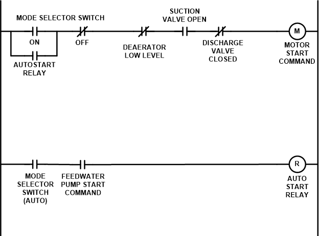
In this circuit, there are two “rungs” to start the motor. The first path starts with the Mode Selector Switch. Notice that either the “ON” OR “AUTO” start contacts will complete that portion of the circuit. The “OFF” position is an XIC (Examine if closed) contact, or in legacy electrical terms a “Normally Closed” contact. This means that if the Mode Selector Switch is in any position OTHER than “OFF,” that portion of the circuit is complete.
The final paths in this rung are the “permissives,” or safety relays. For this circuit, as long as the following things are true, the circuit is complete:
If all of these are met, then the “Motor Starter Contact” (the controller output) is commanded to “Energize” or “Start.” Additionally, since there is no “Latch” relay in our circuit, if any of the permissives are no longer met (or the switch is taken to OFF) the motor relay command will change to “0” and the motor will stop.
What about the second rung of our Ladder Logic diagram? What is the purpose of that rung?
The second rung provides the input to the “AutoStart Relay” on the first rung. In order for the pump to be provided with an “Auto Start” command, the Mode Selector switch must be in AUTO, and the Plant Master Controller must have provided a demand for an additional pump start (more on that later).
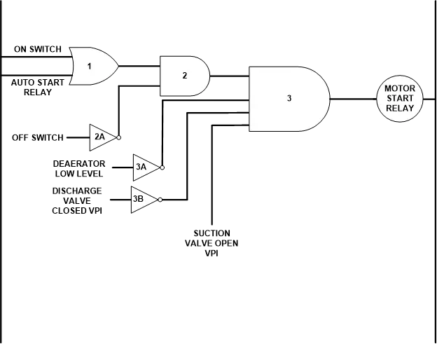
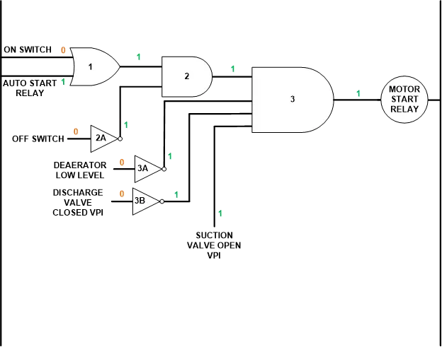
Now that we have a circuit built, let’s take a look at the Logic Gates. Figure 3 shows the logic gates our engineer used to code this circuit. The first step is the “OR” gate (No.1). This gate evaluates the input from the “ON” switch position, and the “Auto Start Relay.” If EITHER of these are TRUE (or 1), then a TRUE (or 1) is sent out of the gate. To prevent BOTH from being true at the same time, recall that the Auto Start Relay will only be energized if the Mode Selector Switch is in AUTO AND the Plant Master sends a demand for an additional pump.
The next gate is the “AND” gate (No.2). This one got a little bit trickier because we wanted the pump to de-energize if the switch position was taken to off, so this logic gate has to see a “1” from gate No.1, AND a “1” from the “OFF” switch. This is accomplished using the inverter (No.2A). If the switch is NOT in the “OFF” position, the input is FALSE (or 0). The inverter flips this input and gives the opposite output (it outputs 1). So, the No.2 Logic Gate sees two “1” inputs and supplies a “1” output.
Finally, our Permissives Gate (No.3), also an “AND” gate, takes the “1” output from Gates No.1 and No.2 and requires that all four signals supplied to it be TRUE (1). There are multiple ways to accomplish these steps, but for our purposes, we used inverters (3A and 3B) to provide the input that the Deaerator Level was NOT low and that the Discharge Valve was NOT CLOSED. The input that the Suction Valve was indeed OPEN is a straight input.
In order to prove that our logic worked, we create a “Truth Table” and use our inputs to calculate the final output. We lay out each gate, and each gate type, and then provide the inputs and calculate the outputs. The standard “Truth Table” diagram for each gate was provided in Part 2 of this series. Table 1 below provides the Truth Table for our Ladder Logic diagram, given the following system conditions:
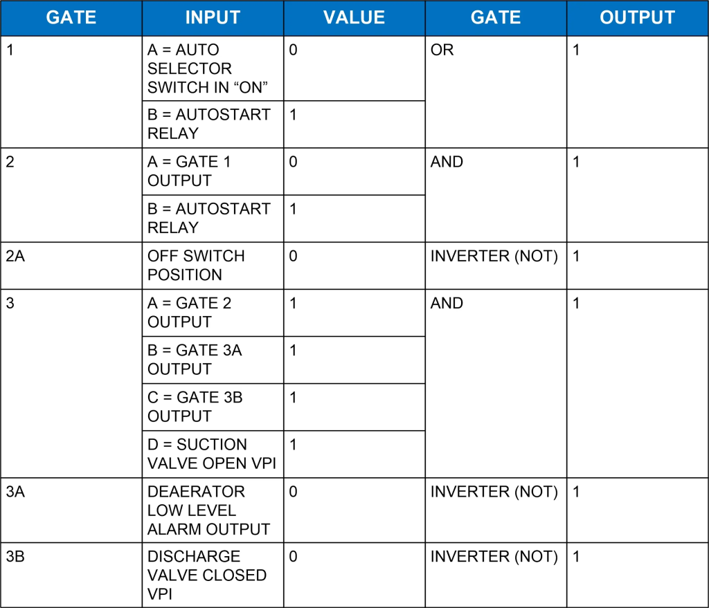
To make it more visible, the logic diagram with inputs/outputs is provided in Figure 4.
As you can see, our logic is satisfied, and the selected feedwater pump starts. Hopefully, this helps simplify the process of microprocessor controls and Ladder Logic. Now you know how to decipher the common language in the programming of individual controllers. There is one other important piece we need to discuss, and that is the difference between “Analog” and “Digital” signals. In our example, the majority of our Inputs were “Digital” or “Discrete.” This means they were, in computer-speak, “ON” or “OFF” (True or False, 1 or 0, whatever you use to describe it). An analog signal is variable, like the signal from a temperature detector, or the output of a flowmeter (i.e., Steam Flow and Feedwater Flow listed previously). So how does a variable signal speak to a computer in yes and no? Next time we’ll discuss the PID Controller and how the terms you learned in Calculus come into play.
For more information or to see how Fossil Consulting Services can decode your hieroglyphics for you, visit us at www.fossilconsulting.com.